A long while back, I used to play “APB: Reloaded”. It was an MMO made by some of the folks behind Grand Theft Auto 3 back in the day. I never played it when it first came, but hopped in once it went free to play. On the surface, you’d think the game’s main hook would be around the shooting and driving mechanics as the core gameplay was a third-person shooter mixed with driving cars. However, the real draw of this game was the character customization. It’s the sort of system that lets you draw anything, but you did it by combining shapes together in a creative fashion. When you saw the stuff people made, it’d be inspiring to make something cool yourself.
Image by IRaulDuke. See all the awesome stuff people make at: https://forums.gamersfirst.com/topic/63-showcase-symbol-customization/
I started to dig into the game some more, and could spend hours making symbols and things to customize my character and car. Eventually, it was really the only reason I played the game, and it became a way I could make art like I never could before, so I began looking for a tool to draw art in a similar way.
Enter: Libre-Office Draw

Libre-Office has a program for drawing diagrams, but in it, you can make whatever shape you want, and you can make all kinds of transformations to get what you’re looking for. I spent some time using it to just try and make some stickers to put on my computer case, but then I thought, what if I used this for making a character animation.
I mean, if everything is basic shapes, then it shouldn’t be too hard to just build the basic parts and shift everything around for each frame. So I thought, I’ll make a simple 2D character in Libre-Office Draw and adjust it for different animation frames.
Trying to do it manually
So, my first thought was, I’ll just manually adjust the character for each frame. Unfortunately, that was a real pain in the butt. The character I made only has a total of 11 shapes: head, neck, upper-arms, lower-arms, torso, thighs, calves. My first goal of making an idle animation ended almost as soon as I got started. I made a key frame, then two, then three, then realized I needed to smooth out the transitions between them. That’s where I realized it was never going to work. I couldn’t smooth out the frames manually, I just can’t eyeball how to adjust it to make it work. Not to mention, it’s incredibly tedious work. All y’all artists out there making animation frames, you heart goes out to you.

Making a Plugin to Automate it
Turns out Libre-Office has a large framework for building plugins and extending the functionality of its programs. So, I figured, why not make a plugin that can try and interpolate the transformations between the two animation frames and generate the intermediate frames.
So it’s time for some math
Libre Office draw will store each shape as a collection of points with individual transformation matrices for each point or in the case of defined shapes (like a square or circle) there will be one transformation matrix for the entire shape. To get the shapes to interpolate properly, you need to break down the transformation matrix into it’s individual components, e.g. Translation, Rotation, Scale, and Shear and do the interpolation on those.
Cubic Spline Interpolation
For this part, originally thought I’d do some basic linear interpolation, but it made choppy transitions between key frames, so instead I switched to using a cubic spline. I wish I could say I was a cool dude who wrote his own spline function, but nope, I just grabbed what I could find on Google. Which happened to be the code here: https://gist.github.com/lecho/7627739
It works really well, 10/10 would recommend.
Breaking down a 2D transformation matrix
I’m writing this article a good while after I made this plugin, and while reviewing what I did, well, I made some mistakes.
Refer to the above transformation matrix layout, when I refer to specific values in the matrix, I’m referencing that.
Let’s start with what’s correct. Translation. No problems here. This is the easy one.
private void getTranslationVector(HomogenMatrixLine3 rowX, HomogenMatrixLine3 rowY, HomogenMatrixLine3 rowZ)
{
    translationVector[x] = rowX.Column3;
    translationVector[y] = rowY.Column3;
}
Next let’s go onto rotation. Also works just fine. Note that this implies a counter-clockwise rotation. If we were measuring a clockwise rotation, then you would need to inverse the sign of ‘b’ (rowY.Column1). But this only works if there’s no shear perpendicular to the x axis. If there is, then this whole thing becomes a lot more complicated.
private void getRotationAngle(HomogenMatrixLine3 rowX, HomogenMatrixLine3 rowY, HomogenMatrixLine3 rowZ)
{
    rotationAngle = Math.atan2(rowY.Column1, rowX.Column1);
}
Now let’s figure out the scaling, and this is where things get trickier, and also where my errors started to slip in because nothing works when the shape has any kind of shear.
Let’s start with scalingVector[x]; it’s fine if there’s no shear. There’s an implication that, because our rotation angle was atan(d, a), a = r*cos(theta) and d = r*sin(theta). So, the magnitude of the vector [a,d] = sqrt(r * (cos^2(theta) + sin^2(theta)) = r. So what, you ask? Well, ‘a’ is also the x scaling value multiplied by cos(rotation). So, altogether, a=r*cos(theta)=scale(x)*cos(rotation) so, r = scale(x).
Now what about scale(y)? Since we’re doing a counter-clockwise rotation, e=scaling(y) * cos(rotation) and b = scaling(y) * -sin(theta). So if I just multiply and subtract cos and sin, then I can get scaling(y) = scaling(y) * (cos^2(rotation) + sin^2(rotation)).
private void getScalingVector(HomogenMatrixLine3 rowX, HomogenMatrixLine3 rowY, HomogenMatrixLine3 rowZ)
{
    scalingVector[x] = vectorMagnitude(rowX.Column1, rowY.Column1);
    scalingVector[y] = (rowY.Column2*Math.cos(rotationAngle)) - (rowX.Column2*Math.sin(rotationAngle));
}

private double vectorMagnitude(double xVal, double yVal)
{
    double magnitude = xVal*xVal + yVal*yVal;
    magnitude = Math.sqrt(magnitude);
    return magnitude;
}
So wait… what about shearing you ask. Well, this is where I failed when I was working on it. In fact, I noticed there was a comment in my code saying “Shearing is not working yet.” This is because I never bothered to break it all down and see the affect shearing has. If I did then I would notice the following:
a = scaling(x) * cos(rotation) + scaling(y) * shear(x) * -sin(rotation)
b = scaling(y) * -sin(rotation) + scaling(x) * shear(y) * cos(rotation)
d = scaling(x) * sin(rotation) + scaling(y) * shear(x) * cos(rotation)
e = scaling(y) * cos(rotation) + scaling(x) * shear(y) * sin(rotation)
At this point, I’m tired of messing around with it, and say whatever, who needs a shear anyway… And there’s a decent thread on how to break down a 2D transformation matrix that only shears on one-axis here: https://stackoverflow.com/questions/45159314/decompose-2d-transformation-matrix
Either way, even without shearing, at this point I’m able to test it out and see if it’s even worth continuing the effort.
Here’s how it turned out
Long story short, it really depends on how you make each key-frame. For example, if you make a key frame by copying the previous frame and making small adjustments, then it works great, but if limbs are rotating 180 degrees and flipping orientation, then it gets problematic.
For example, the idle animation I started seems to interpolate fairly nicely.

But then I tried to do some kind of cool spinning punch move…
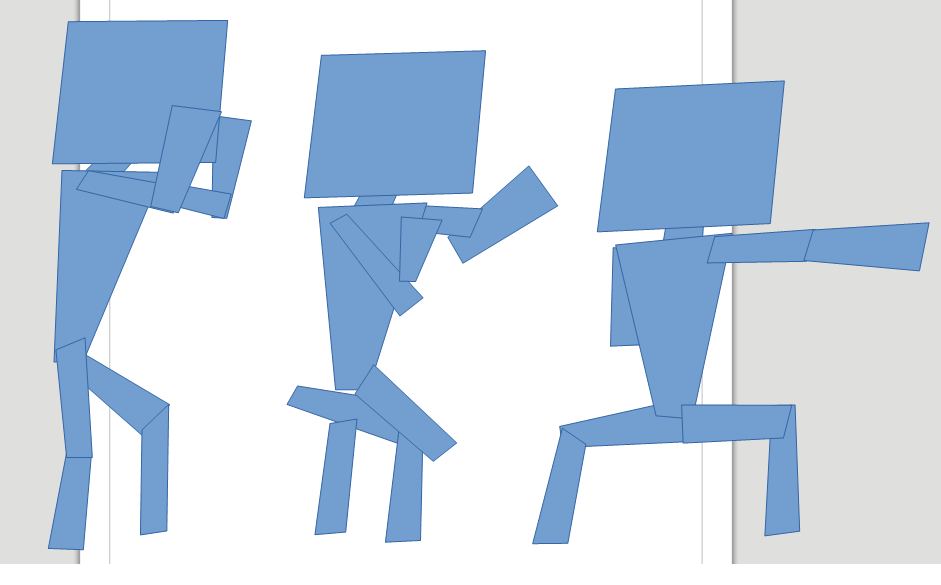
That’s where everything broke down. The arms and legs all got disconnected, and it’s just a mess. However, there still is hope, because the shape of the limbs seem like they might be right, it’s just the positioning that’s all broken.
If I rearrange everything to be in the appropriate place then…
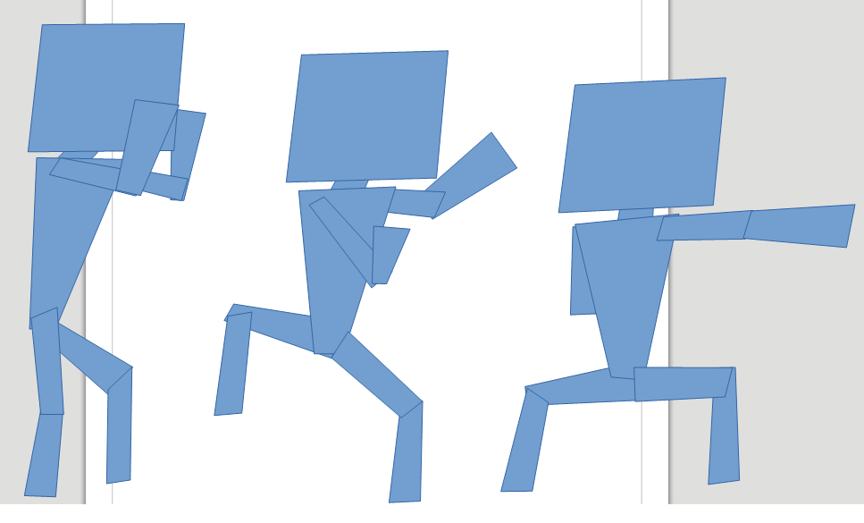
It looks halfway decent now. I mean, it’s still a bad animation, but maybe this was just too big a jump and if I put a key frame in between I can get some better results. At least the only manual work I needed to do was move some shapes around which is a lot easier than doing the rotation and point manipulation of the shape itself.
All in all it’s a fun little experiment and I was actually kinda proud of the animations I made using it for this simple character. I can’t imagine making a complex character with this tool however, it’d be a lot of work, but then again, so is animation in general.
But anyways here’s how those two animations looked at the end of it all. I added a few more key frames to the punch and interpolated about 4-5 additional frames between the two using my plugin.

Conclusion
While it was a fun experiment, there’s a lot more work to be done if you ever wanted this to be viable. Honestly, it’d probably be easier to make a 2D skeleton and animations using Blender or something like that. The whole idea of bones, joints, and skeletons solves the problem of keeping things aligned, and game engines can take advantage of those to do their own animation blending without the need for sprite sheets.
Code and Stuff
Plugin code is available on GitHub here: https://github.com/PickledMonkey/ShapeInterpolator
